Q.monixx APP1: Architecture pattern for the test.con application design
1 Introduction

The application of a universal architecture pattern was proposed, in order to receive an application design for the application development with test.con which is as transparent and comprehensive as possible. For this architecture pattern, the ideas and views of the organization http://www.arc42.de/ will be used.
The central architectural views from arc42 offer a basic introduction into the architecture pattern. Beside arc42, the architecture is influenced by the ideas and concepts from the service-oriented architecture (SOA). In this case, the business logic will be programmed as a flow chart. The services will be primarily programmed in CFC.
2 Architectural views
Context chart
Context differentiation → In which professional and/or functional environment does the system work?
Block view as Continuous Function Chart (CFC)
This view shows various aspects of a software.
- All ongoing software processes in a classic signal flow chart
- Services within the meaning of SOA that are controlled by other elements within the runtime view (activating / mode switching...)
- The static structure of the system, the setting of implementation parts
Runtime view as a flow chart
Various aspects of the software are shown here as well
- The implementation of the time sequence of the software business logic (system processes) → these elements control the services in the CFC
- The implementation of functions which contain more status-orientated and only a few continuous aspects
- The implementation of the time sequence of pages (page flow) in a GUI.
Distribution view
This view shows, on which hardware the blocks are called. This view is used for complex systems and here especially for a central system design based on simulation models.
3 Representation of the architecture using the example Q.monixx-APP1
General functional description of the Q.monixx-APP1
START-APP
The universal START-APP is a very special test.con application as this software builds the content generically and, in this sense, it does not comply with the normal conventions of the software that is described here. For this reason, that part of the application is not described in this document.
Using the tile "My Application" you can go back to the demo application MY_APP
MY_APP
MY_APP is a simple application which shows both input channels AI1 and AI2, whereby AI1 is configured as resistance channel and AI2 as temperature channel. The application features 4 process states (called business processes within the context of SOA). This application does not have a real purpose. With this application, only the principle of SOA and the architecture documentation arc42 should be described.
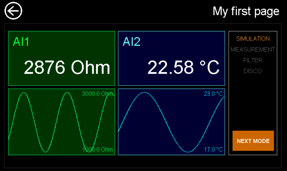
- Business process – SIMULATION In this business process, all values of both input channels are simulated by sine functions
- Business process – MEASUREMENT In this business process, the analogue input values are actually captured and unfiltered transmitted to the displays
- Business process – FILTER In this business process, the analogue input values are actually captured, filtered (low pass) and transmitted to the displays.
- Business process – DISCO In this business process, the tiles of the display will be shown as a counterclockwise running light
4 Configuration level as access to the architectural views
In test.con, the architectural views do not serve only for documenting the architecture, but are also an integral part of the executable software. The access to the three primary architectural views: context chart, block view and runtime view starts from the topmost view, the configurations view. Normally, the program blocks are placed on the configuration level.
The block view and the runtime view represent a program paradigm which is totally different. As in text.con the architectural views lead directly to executable software, the system must call the views also in an autonomous context. Program blocks offer such autonomy, and they are well suited as access to the different architectural views.
NOTE: It exists a current version: V1.0.0.1. of the application/template. This version can be downloaded from the download area in testcon.info.
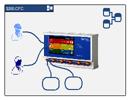
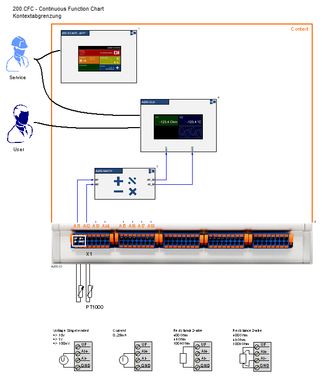
200.CFC
Block view CFC - Continuous Function Chart with a context chart on the first level
Context chart (context differentiation)
Within the demo project, the description of the context is very simple. Only the two stakeholders of the application and the two configurable sensors are shown. The connection to the technical process is documented in a real process. (e.g. the precise position where a temperature sensor is connected to the motor)
300.PCC
Runtime view 1 PCC – Process Control Chart: the time sequence of the software processes

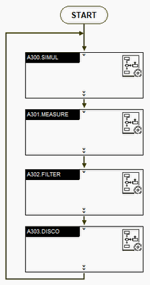
Process Control Chart (PCC)
Here, the time sequence of the business processes will be documented as a flow chart
100.PFC
Runtime view 2 PFC – Page Flow Chart: the time sequence of the calls of the GUI pages
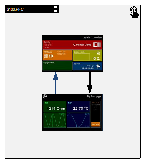
Page Flow Chart (PFC)
On the topmost level, we see the two main pages of the demo application
- Page SERVICE with the START-APP
- Own application MY_APP
5 Block view/service in CFC
The block view shows the functional components with their data connections. This view can be described as static view, as it does not state when which component is called. Within the context of the programming in the CFC this means concretely that always all functions are called virtually continuously. During the programing, the order of block processing will be set manually. This is necessary as this architecture should be directly transformed in an executable program.
Level 1
Connecting the functional main components
- Capture values
- Signal processing
- Update the displays
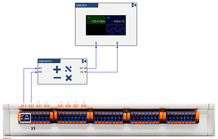
A202.MATH
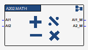
Functional component: signal processing
In the context of SOA, this is a collection of services under the control of business processes. (activate, deactivate, etc...)
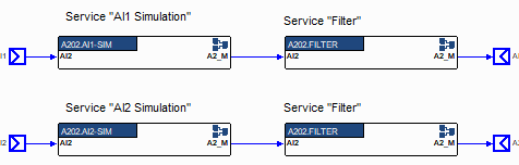
Integration of the individual functions (services) into the signal flow
A200.GUI
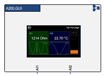
Functional component: Updating the display values in the GUI
Within the context of SOA, the actualization of GUI displays is a service under the control of business processes (activate, deactivate, etc...). Furthermore, the controlling of displays can be a service (see also DISCO Service)
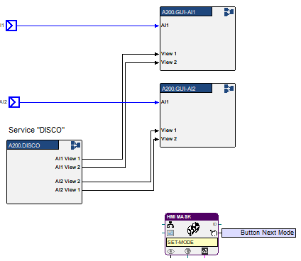
Integration of the individual displays (services) into the signal flow
6 Runtime view
In many applications, the page flow of the GUI and the time sequence of the software processes are drawn in separate flow charts, as the states of both flow charts are not always identical. But there are also applications where the PCC and PFC are joined in one PFC and where the PCC is omitted.
Process Control Chart (PCC)
In the context of SOA, the time sequence of the business processes is defined here.
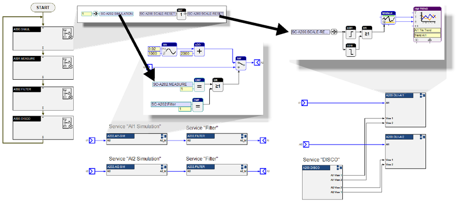
A300.SIMUL
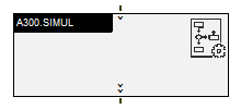
The business process block is designed as a flow-chart block. In general, this block does not contain the actual functions, but controls the functions by variables.
A300.SIMUL-Diagramm
All business processes have an identical layout to a large extent.
- Entry in the process (INIT) → will be called one-time during the entry
- Runtime of the process (RUN) → will be called in the cycle time of the program block

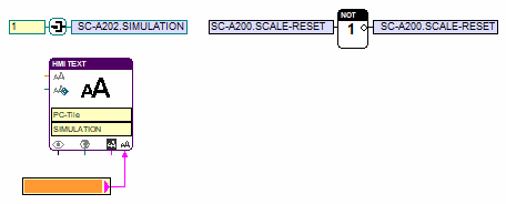
A300_INIT
Entry in the business process
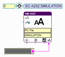
- The variable SC-A202.SIMULATION will be set to one = Service SIMULATION should be activated
- The SC-A202.SCALE RESET will be toggled = The services for the Update of the chart view should carry out a reset for the automated calculation of the Y scale
- The text display for the activation of the process SIMULATION should be switched to orange.
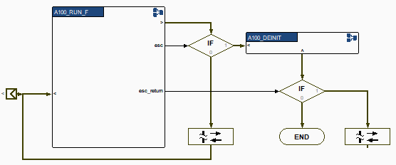
A300_RUN
A RUN function with a simple navigation, leading to other states. See 101_RUN as an example for more complex RUN functions.
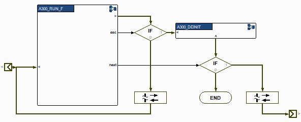
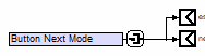
A300_RUN_F
In RUN_F, only the variable for the button "Next Mode" will be interrogated and transmitted to the outputs esc = exit the process and next = next process.
At more complex processes, all conditions for the exiting of the process are programed in this place. The output esc must be set to HIGH at every exit condition. The next process step can be defined via the outputs for the respective conditions.
A300_DEINIT
In DEINIT will be called when exiting the process. Hereby only the service "SIMULATION" will be deactivated via the variable. The display which shows the active process state will be set to grey.
All other business processes have an identical structure.
Page Flow Chart (PFC)
The page flow chart is a special runtime view which shows only the time sequence of the page views. But the connection between the page flow and the business processes is so close in some applications that the business processes can be viewed using the page flow.
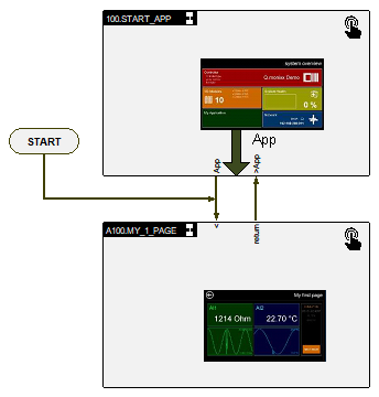
100.PFC
Page flow between the two APPs
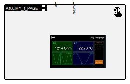
A100.MY_1_PAGE
Main page of MY_APP
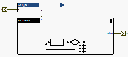
A100.MY_1_PAGE - Diagramm
As MY_APP has only one page, the page control charts start already on the first level with INIT and RUN blocks (see PCC)
- Entry into the process (INIT) → will be called once during the entry
- Runtime of the process (RUN) → will be called during the cycle time of the program block
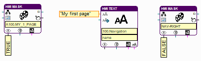
A100_INIT
The following functions are realized with this block:
- Switch mask (page) to visible
- Set the information text in the navigation bar
- Switch the button Return in the navigation to visible
A100_RUN
RUN function with a simple navigation to other pages (to the START_APP)
See 101_RUN as an example for more complex RUN functions.
100.START_APP
Main page of the START_APP
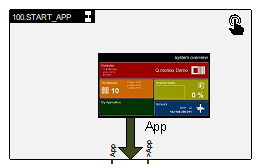
100.START_APP Diagramm
The START_APP has various pages so that a further page flow chart appears on the first level.
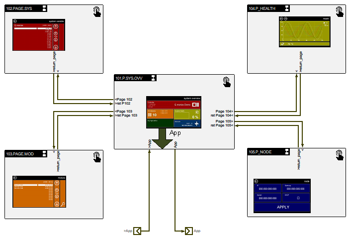
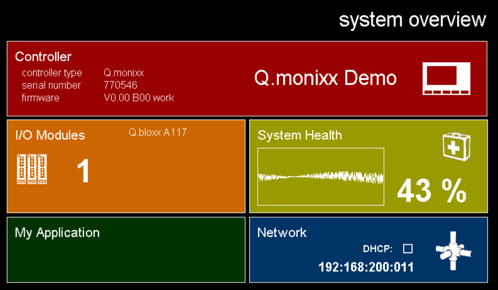
101.P.SYS_OVV
The main page with the system overview and navigation to the subpages by clicking on the tiles.
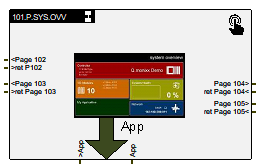
101.P.SYS_OVV-Diagramm
Page Control Chart with INIT and RUN

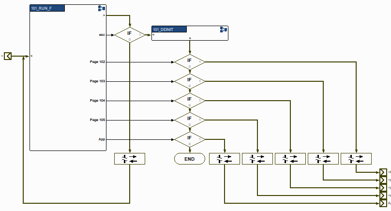
101_RUN
A complex navigation to other pages is shown here
7 Service-oriented architecture (SOA)
Regarding text.con, in SOA the business processes are programed in a flow chart and the services in CFC. The business processes control the state of the services via variables.
Background for this procedure
Services
The function (service) in the measuring technique has to be seen in the context of the signal flow. Furthermore, in architecture or design the principal capabilities of the system should not be linked to time sequences.
Business processes
However, the business process is closely linked to the time sequences of processes. Here, specific signal paths play hardly a roll. In this context, it is only important which process transitions exist and in which process step the system currently is. Details to the actual functionality are subordinated at this view.