Online observation
1 General
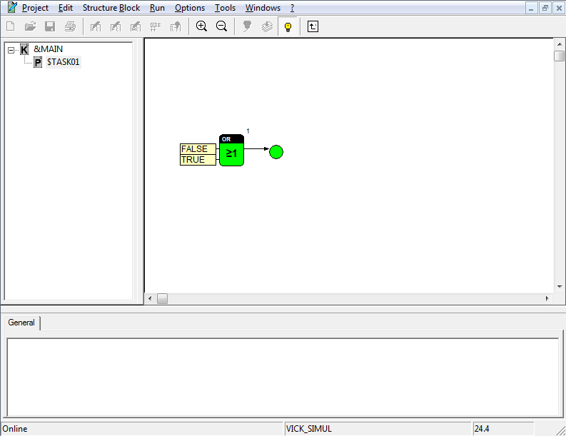
After successful loading the user program, the system automatically switches to Online Observation. For observing a program that has been already loaded, call the Online command in run submenu after logon to the target system.
In the Online Observation state visualization blocks read the values of the connected signals cyclically and display them in the block symbol. A number of blocks with target functions also display their internal switching states. The relevant visualization functions are described in the help for the blocks.
The values of other signals can be checked by means of the display dialogs for the connections. Parameter and editing dialogs can be used for changing values in the target system. Special blocks trace and record signal values and, hence, serve to analyze the program's behavior.
The name of the target system and the system time are displayed in the status bar.
The following sections describe operations, which can be performed during Online Observation of the program.
2 Display signal values
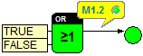
If a signal is connected with a visualization block, its values are cyclically read out in the Online Observation mode and displayed in the block. Visualization blocks for standard data types are contained in the library of the same name. The intervals for cyclic updates of values can be set via the refresh rate in the dialog Worksheet Setup (Options submenu).
The following operations need to be performed to display signal values without any visualization block.
Procedure
1. Click a connection by pressing the left mouse button
A window containing the logic address of the signal is opened. In addition, the designation and a comment are displayed for parameters. Following the first read-out of the signal value, this signal value is displayed beside the logic address. Subsequently, the display is updated at a rate identical to that of the other visualization blocks.
By pressing the left mouse button again, the display is closed.
The type of display depends on the data type of the signal. LEDs are used for bits and bytes. In other cases the numerical or text values are displayed.
3 Change parameters and signals
In the Online Observation mode, changes in parameter dialogs of blocks do not only exert an influence on the project, but also on the working process in the target system. After closing a dialog, any values entered are transferred to the target system and changed there in the memory (RAM). To copy changes to the non-volatile storage area in the target system (Flash, EEPROM, HD, etc.), the Parameter button in the Logon to Target System dialog needs to be pressed. It depends on the target system whether or not this operation can be implemented and what their effects are; reference is made to the relating documentation. Of course, target systems without any non-volatile storage, such as simulation, will not support writing of parameters into non-volatile storage.
The values of signals and parameters can be also changed via online editing dialogs. These entries will only have an effect on the target system and do not influence the project.
Procedure
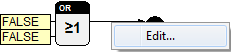
1. Call the context menu for a connection
By clicking the line segment of a connection with the right mouse button, the relating context menu is called.
2. Call the Edit command
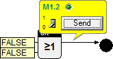
A window with the logic address of the signal opens. For parameters it may additionally contain their designation. Apart from the logic address, the current value of the signal is visualized.
3. Enter the new signal value
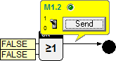
The new signal value can be entered via a control element in the opened window. The type of the control element depends on the data type of the signal. For instance, buttons are used for bits and bytes, whereas input fields are available for numerical and text values.
4. Send
Upon pressing Send, the new values are transferred to the target system and stored there in the RAM. Press the right mouse button to close the window without changing the signal value.
The effects of the change may be traced by means of visualization blocks or display dialogs.
For signals which are cyclically overwritten by blocks, it is often not worthwhile to intervene from outside as the change would not have any influence on processing in the target system. The depicted example will often have no visible change, because the changed value will be overwritten at once. Only with slow cycle times or if the part of the program is currently not executed the change of the display will be visible.
4 Read and write parameters
Commands are provided to match parameters in the project and in the target system by reading all parameter from the target system or writing them in the target system. Before these commands are used, the system should be switched to Online Observation by using the Online command after logon to target system.
Procedure to read all parameters from the target system
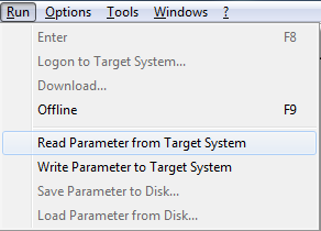
1. Call the Read Parameter from Target System command in the Run submenu
Upon calling, a message is displayed asking to confirm the process. The communication requirements for reading all parameters may be a burden for the target system and take time for large projects.
2. Confirm the request for confirmation with Yes
The blocks read their parameters from the target system. The project is updated.
Procedure to write all parameters to the target system
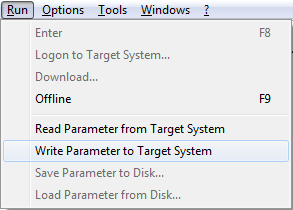
1. Call the Write Parameter to Target System command in the Run submenu
Also under this command, a request for confirmation is displayed to prevent accidental calls.
2. Confirm the request for confirmation with Yes
The parameters of all blocks are transferred into the memory (RAM) of the target system. This process might take some time. To change parameter values in the non-volatile storage area of the target system (for reboot purposes), the Parameter button in the Target System dialog must be pressed after the system has been switched into the Run mode.