Theoretical background
Basics: Programming with blocks
An application program is programmed in a so-called Continuous Function Chart (CFC). But what does that mean really?
By drawing a block diagram, a program is being created. Function blocks are therefore placed on a worksheet and the inputs and outputs are being connected to each other. After such a network made of function blocks and connection lines is drawn, a network description written in a language readable for machines is uploaded on the mini PLC.
The name “Continuous Function Chart” already indicates, that the application program is a network made of blocks and connection lines, running as a continuous process. Just like in an electronic circuit, in which logic gates as f. e. AND and OR are continuously executed, the function blocks in the mini PLC are also continuously called.
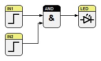
As shown in image 1, the blocks IN1, IN2, AND and LED are constantly called from the PLC. The blocks IN1 and IN2 are continuously reading the current voltage at the digital input terminals 1 and 2, they convert the value into a logic signal (0 or 1) readable for the program. The result for this translation is written on the output as a logic 1 or 0 signal. The value is transferred to the AND block over the connection line. At the AND block, the logic algebra of the AND function is executed and the result of the algebra is written on the output (1 or 0). The connection line transfers the value to the LED block. There, the logic signal 1 or 0 is converted into the corresponding current signal and accordingly, the LED is illuminated or not.
Function blocks (FB)
The function block is the smallest applicable unit of an application program in the PLC-related world. It is the central programming medium in our graphical programming system.
Function blocks can have several output variables and allow the same input values for different output values. That is possible, as it also has internal variables, whose values are preserved even after the block was called.
Function blocks are parametrizable by using input, output and inner variables. Function blocks are always called by program blocks in miCon-L. The call is done by instantiation. The instance is comparable with a copy of the block for a special application case, whereas the necessary memory range is made available. The data is saved between the block calls. This circumstance is commonly called the “memory” of the function block.
In the PLC-related world, functions and function blocks are being distinguished. Here, the function, f. e. an addition, has no memory. However, there is no such distinction in miCon-L. All blocks are called function blocks there.
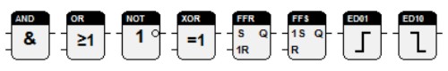
A catalog with all function blocks available for miCon-L you can find under Function blocks.
Continuous Function Chart (CFC)
Translated from the German Wikipedia article: Continuous Function Chart
The Continuous Function Chart (CFC) is a programming language for Programmable Logic Controllers (PLC). Even though it is a language, which is not defined in the IEC 61131-3 standard, it is still an established extension of the IEC programming environment.
Its main field of application is in process control engineering, as complex control and controller tasks occurring in that area can be drawn very well in a CFC.
CFC is a graphical programming language, in which function blocks are connected with each other, instead of implementing a series of textual commands like in classic programming languages. It is following the pattern of circuit diagrams from hardware development. This type of appearance of a program comes in handy for developers of control software, as their technical background is typically in electrical engineering.
CFC can be seen as extension of the function block language, in which no strict line-by-line processing from top left to down right is forced. The function blocks can be positioned freely and the programmer has more possibilities to connect the inputs and outputs.
The function blocks in miCon-L were programmed in the programming language C and are delivered as standard blocks by the manufacturer of the PLC.
Advice and tips
Golden Rules for methodical software development with graphical programming software
A maximum of self-documenting structures is developed because there always is a connection to the specific application context.
Use as many information from the functional specifications as possible. If there are strong diagrams or block diagrams with significant symbols, try to use those diagrams and symbols in the graphical programming system again.
Tip: Application-specific symbols have high implicit information content. You should take the time to use those symbols in the graphical programming system. When you have to change the software some years later, you will appreciate each and every information that you can get.
In the present HDA 10 project, the functional specifications were ideal preconditions to apply the golden rule. The diagrams reflect the context of the application perfectly. Furthermore the diagrams support the application of the top-down draft procedure.
Right use of the software resource
The development and maintenance of technical systems is in a change, as embedding micro processing units is getting more and more complex. Role models rarely exist in that extent. Classic engineering disciplines like machine engineering, process engineering and electrical engineering are confronted with the individualized world of software development because of growing development and quality standards. While in classic engineering science a high attention for documenting ideas, processes, constructions or formulas is payed, many companies are quite careless about documentation, when it comes to the carefully developed software solutions. However, it has commonly been known for a long time that the added value potential of technical systems is determined by the efficiency of the software development.
Even though many projects fail because of software problems, the value of good software solutions is barely recognized and is not documented well enough because of high time and project pressure, so the software cannot be reused.
While process technicians, electrical engineers and machine builders had many years to agree on defined interfaces, software solutions are now rapidly replacing slowly grown development processes. However, software projects are often realized without the basic principles or methodical proceedings. Especially in the sensitive area of embedded systems, some companies are characterized by individual, tricky solo programming. The reason for that is rather the missing tools than the missing awareness of the problem. In machine and plant engineering the hardware solutions are assembled from cataloged, CAD-supported standard modules and special developments are only made for specific parts. In software development, however, it could happen that the same functions are programmed multiple times, as a useful cataloging and presentation of the developed software functions is missing. Flexibility and individuality are indeed two reasons for the successful implementation of software in almost all technical areas, but they are an enormous challenge for mastering the systems as well. Never before has a technology affected other technological disciplines as deeply and profound.
To see technical software as valuable goods and to develop and document it accordingly and responsibly will be one of the most important competition criteria of the future.