PID Controller (Universal)
Symbol (samples)
[A]
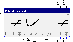
Without limit controller output
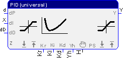
[B] Disturbance feed forward and with limit inputs
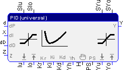
[C] Disturbance feed forward
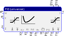
[D]
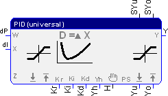
The function block PID Controller (Universal) contains the following elements:
- proportional term
- integral term
- differential term
- integral wind-up avoidance logic
- setup of controller output; with auto/manual selection
The function block supports four types of PID controllers. Depending on the selection, there are different input and output connectors available.
|
Type 1 [a] |
Shared error input for P-, I- and D-term |
|
Type 2 [b] |
Individual error input for P-, I- and D-term |
|
Type 3 [c] |
Setpoint and controlled variable as input, the error input d (d=W-X) is set in the controller |
|
Type 4 [d] |
Setpoint and controlled variable as input, the error input d (d=W-X) for the P- and I-term is set in the controller, for the D-term it is calculated from the change of the controlled variable. |
The input pins must be connected. The controller subtracts the disturbance (Z) from the controller output before it is limited.
The controller can be tuned by the multiplier (Kr) and by the multipliers (Ki, Kd) or by the time constants (Tn, Tv). Internally, a calculation with the coefficients is taking place. If the reset time Tn turns to 0, the I-proportion is turned off.
If parameter pins for the limitation are activated, they have to be connected. The limitation takes place inside the block. The output limitation is used to prevent a wind-up. If the output limitation is not done properly, the integration sum will be frozen.
If the input disturbance (Z) activated, the preset input (PS) will be available. Setting it means the the input disturbance (Z) is set on the output.
Setting the manual mode (H) will lead to the manual set input (Yh) on the output. The manual mode is dominant over the preset input.
A limitation of the setpoint will also be effected, if the preset or manual input is set.
At the output, either the Controller output (Y) or the change of the output (dY) can be output.
If the limitations are exceeded, the outputs SYu or SYo are set.
Parameters
The parameter dialog can be used to select the type of the PID controller and several variations within each type. The available input and output connectors can be selected and the interpretation of the input parameters (time based or coefficient) as well as the terms, which have an effect on controlling (PID, PI, PD), can be defined.
Operations
Legend:
T Cycle time
Signals
| Name | I/O | Type(s) | Function |
|---|---|---|---|
| d | I | FLOAT | Error input [a] |
| dP | I | FLOAT | Error input; P-term [b] |
| dI | I | FLOAT | Error input; I-term[b] |
| dD | I | FLOAT | Error input; D-term [b] |
| W | I | FLOAT | Setpoint [c], [d] |
| X | I | FLOAT | Controlled variable (sensor input) [c], [d] |
| Z | I | FLOAT | Disturbance (disturbance feed forward) |
| Iu | I | FLOAT | Lower limit inputs |
| Io | I | FLOAT | Upper limit inputs |
| Kr | I | FLOAT | Proportional multiplier |
| Ki, Tn | I | FLOAT | Integral multiplier, term integral time constant in [s] |
| Kd, Tv | I | FLOAT | Differential multiplier, term differential time constant in [s] |
| Yh | I | FLOAT | Manual set input |
| H | I | BIT | Manual mode |
| PS | I | BIT | Disturbance mode, Preset (disturbance feed forward) |
| Yu | I | FLOAT | Lower limit controller output, wind-up |
| Yo | I | FLOAT | Upper limit controller output, wind-up |
| SIu | O | BIT | Lower limit (error W-X) reached |
| SIo | O | BIT | Upper limit (error W-X) reached |
| SYu | O | BIT | Lower controller output limit (Yu) reached |
| SYo | O | BIT | Upper controller output limit (Yu) reached |
| Y | O | FLOAT | Controller output |
| dY | O | FLOAT | Controller output (y[n] - y[n-1]) |
Parameters
| Ki | = 0 | I-term is off |
| Tn | = 0 | I-term is off |
| Kd | = 0 | D-term is off |
| Tv | = 0 | D-term is off |
| H | = 1 | Manual mode - Yh is channeled directly to Y (dominant) |
| PS | = 1 | Disturbance mode – The signal Z is channeled directly to Y |
Examples
Controlled system: PT1-term (T1=4)
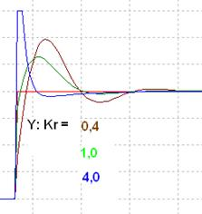
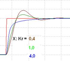
Ki=0,5 Kd=1,0
Step response, change proportional multiplier
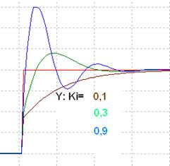
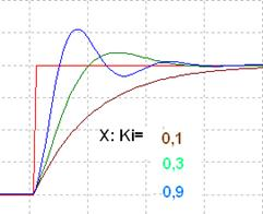
Kr=0,5 Kd=1,0
Step response, change integral multiplier

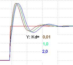
Kr=0,5 Ki=0,7
Step response, change differential multiplier
Visualization

The symbol indicates, whether the controller runs in automatic or in manual mode.
