Program display with Page Flow Diagram
2 Characteristics of a simple HMI page
4 Name conventions for macro blocks
5 Apply the PFD in a specific application
1 Introduction
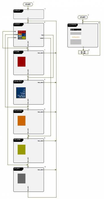
With the Page Flow Diagram (PFD), you can program software solutions. They contain control and indicating elements, which are arranged over various sites and masks.
Generally, the Page Flow Diagram is a Flow Chart Diagram for calling/making visible HMI masks. The main difference is that basic elements of the Flow Chart Diagram are capsuled in macro blocks, f.e. an IF command cannot be seen on the upper levels.
You can find the shown template, when opening a new project with the Standard application (HMI DPA).
2 Characteristics of a simple HMI page
The following description refers to the implementation of a specialized HMI project template, but it can be transferred to other applications, too.
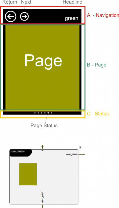
A simple page has one access and two exit points in the standard PFD (page macro). Over the PFD, not the whole display page is made visible, but only section B. The complete display page consists of mask A “navigation”, mask B “page” and mask C “status”. A and C only exist once in the project and are always visible. These sections do not belong to the actual page. The buttons Return and Next are evaluated by the page mask C “navigation” and lead to the exit of the page over the corresponding exit points.
Basic rule 1: Each page checks the requirements for exiting itself. There is no central mechanism which controls the exiting of the page.
Basic rule 2: During access, each page has to provide, that all requirements are fulfilled to function correctly.
The content of the headline is also described in the page macro. The central page macro can be implemented in the Page Flow Diagram (PFD) in any place.
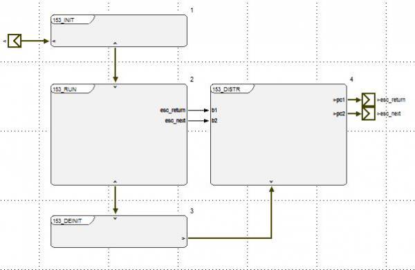
3 Page Control Diagram
Below the central page macro, there is the Page Control Diagram. The PCD basically has the same structure for each page and consists of the macro blocks:
- INIT
- RUN
- DEINIT
- DISTRIBUTOR (DISTR)
4 Name conventions for macro blocks
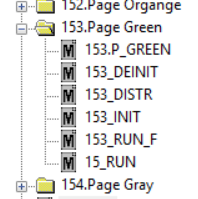
In test.con, macro blocks must have unique names. To keep the names in the PFD and the PCD simple, a 3-sign prefix should be given to all macro names of one page. In experience it has been proven to put numbers on the pages. For that reason there is a three-digit number in the templates for the page prefix.
<xxx>.Page name:
- <xxx>_INIT
- <xxx>_RUN
- <xxx>_DEINIT
- <xxx>_DISTR
INIT
- Make the main page visible
- Overwrite the headline
- Status of the LED for the status display in the status mask
- All further functions, which have to be executed during access into the page, have to
- F. e. read the configuration form an INI file
- …
RUN
- Check Return and Next buttons in the navigation and set requirements to exit the page.
- All other functions, which have to be executed cyclically while the page is visible
- Read and show process values, which only have to be read when the page is visible
- Call graphical objects to implement parameters
- …
DEINIT
- Turn off the main page of the page
- Turn off the LED for page display in the status mask
- All other functions, which have to be executed when exiting the page
- F.e. write a new configuration in an INI file
- …
DISTRIBUTOR
- Check switching conditions, which lead to exiting the page and set the Flow Chart path (execute IF command)
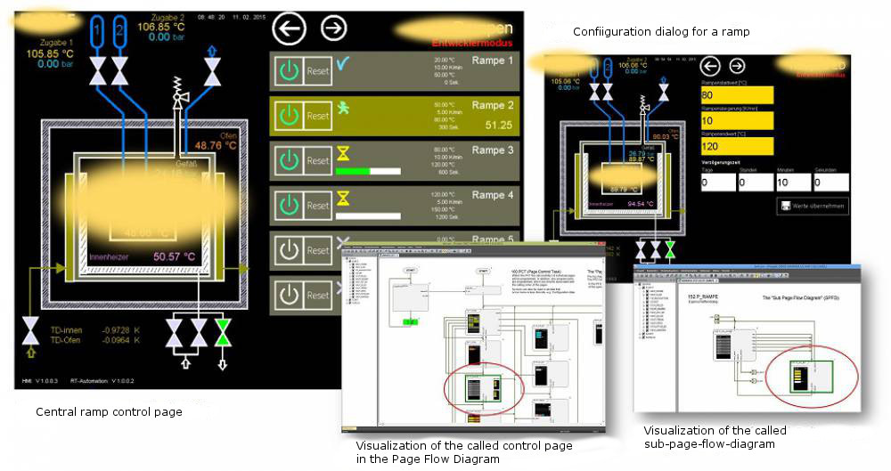
5 Apply the PFD in a specific application
In the specific application only the right site of the screen is controlled over the PFD, not the whole HMI. Furthermore you can see the use of a Sub Page Flow Diagram (SPFD) in this example.
6 Tile-design conventions
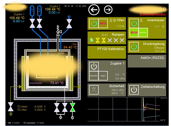
Many HMI applications are designed in a tile-design convention. To apply this design template we recommend to apply these conventions.
The application of these conventions is shown is a specific application example.
- Single components/system characteristics are represented as tile
- The main status of a component is represented as tile, which changes its colored all-over
- Important sub-status information and control elements are implemented as sub tile
- The central configuration dialog for a component is called by clicking on the main tile (if there is no sub tile with control functionality)