Power Measurement Application
1 General Overview
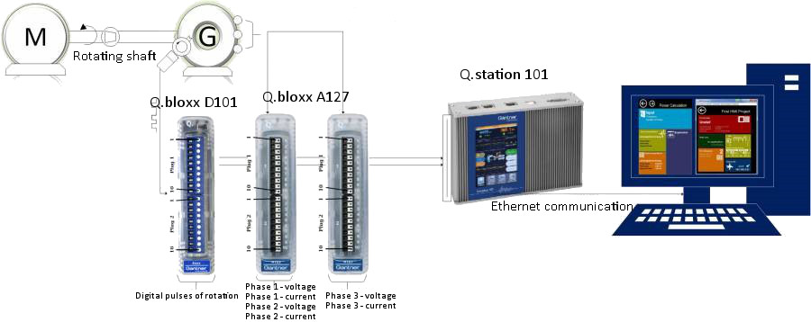
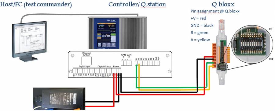
The example for a power measurement application shows the approach of a project using the programming system test.con, the configuration program test.commander, the Test Controller Q.station and Q.bloxx modules. There is a short overview about technical details of the Q.station and the Q.bloxx modules. Furthermore the configuration of the modules and the Q.station in test.commander is presented. An example project for test.commander and test.con are available as download.
The power measurement application includes measuring the current, voltage, real power, apparent power, power-factor, frequency and rpm of a three-phase-machine. The main components required for this application are:
- Q.station 101,
- Q.bloxx A127 and
- Q.bloxx D101.
The power measurement is performed using a Q.bloxx A127 module which ensures a high voltage input. The digital pulse from the Hall effect sensor (pulses of rotating teeth) in the generator is given to the Q.bloxx D101 module which is used to obtain the rate of rotation.
The Following is an overview of the application:
1.1 Working Principle
A normal three-phase-generator running with 50/60 Hz with a speed of 1500/1800 rpm provides a rated output voltage of about 400/230 volts. The output power of the generator (real power and apparent power) can be calculated using the Q.bloxx A127 module. The voltage, current and digital pulse values are read using the Q.bloxx module which is connected with the Q.station. In the Q.station, the values are manipulated to obtain the desired results. The values can be visualized on the HMI display or on a computer display.
1.2 Input Signals and Desired Results
Following analog inputs are needed for the Q.bloxx A127 module:
- Phase 1 - Voltage
- Phase 1 - Current
- Phase 2 - Voltage
- Phase 2 - Current
- Phase 3 - Voltage
- Phase 3 - Current
The following digital input is needed for the Q.bloxx D101 module:
- Digital pulse (rotation of shaft)
For the calculation of frequency and rpm, the following input should be provided by the user with an HMI screen:
- Number of poles in the generator
- Number of teeth in the rotating shaft
The Q.bloxx D101 module is only needed if the user wants to get the frequency and rotation value.
The following results for a three-phase-generator (L1, L2 and L3) can be obtained:
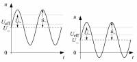
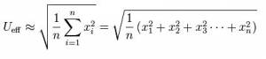
1. For the RMS value of voltage (Volt), the following formula is used
Abbreviations
x is the value of voltage obtained with a sampling frequency of 5 KHz.
n is the number of value sampled over a full period.
Ueff is the rms value of the Voltage signal (volt).
The effective value is taken with respect to zero crossing of the signal. In test.con a triggered average block is used for calculation purpose.
2. RMS value of current (Ampere)
The Irms value for current is calculated in the same manner as the Voltage (Ampere).
3. Real Power (W)
P = 1/T ∫[(Ul(t)*Il(t)] (watt)
Abbreviations
P - Real power (watt)
Ul - Ul1 or Ul2 or Ul3 voltage (volt)
Il - Il1 or Il2 or Il3 current (ampere)
4. Apparent Power (VA)
S=Vrms*Irms (volt-ampere)
Abbreviations
S - Apparent power (VA)
Vrms - root mean square value of voltage (volt)
Irms- root mean square value of current (ampere)
5. Power Factor
Power factor (cos phi) = Real power/Apparent power
6. Frequency (Hz)
The frequency is calculated with the following formula:
Frequency = (N*P)/120 Hz
Abbreviations
N - Speed in rpm
P - No. of poles
7. Speed (rpm)
The speed of the motor (in rpm) is calculated using the D101 module. The variables are configured for 4/120/180 teeth.
⇒ Example: When the Hall effect sensor reads the rotor with 4 teeth, it gives four digital pulses per single rotation.
The module D101 calculates the number of rotations per minute (rpm).
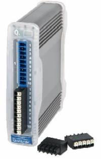
2.1 Q.bloxx A127
The Q.bloxx A127 module is used for measuring electrical power. Following is the description about the Q.bloxx A127 module:
- 4 Voltage input channels:
- 2 inputs for voltage measurement (up to +/- 1200 V)
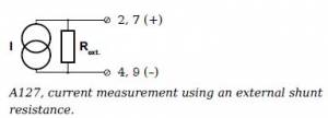
- 2 inputs for current measurement via shunt resistors (up to +/- 2400 mV)
- 24 bit ADC, 50 kHz sample rate per channel with 4 active channels
- 100 kHz sample rate per channel with 2 active channels
- Galvanic isolation: Isolation voltage 1200 DC/858 VACrms
⇒ Further hardware information about the Q.bloxx A127 module.
Current: An external shunt resistance for current measurement is needed.
Voltage: A voltage difference of up to +/- 1200 V can be measured.

The Q.bloxx D101 module is used as a counter in this application. The digital pulses are given as input.
The rotation (rpm) can be calculated using this module.
⇒ Further hardware information about the Q.bloxx D101 module.
The input voltage range must be between 12 V and 30 V.
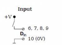
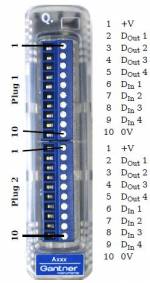
The input pins are connected as shown in the figure.
3 Connecting Modules with the Q.station
The Q.station 101 is a highly flexible controller which has a Linux kernel and is used for custom applications. It has an internal micro controller with 1 GB RAM, with a battery-buffered real time clock and programmable watchdog function. Data can be transferred over the Ethernet interface.
3.1 Setup
Take the Q.station 101 out of the packet and fix it in the metal frame base. The Q.station has a power socket and an RS485 communication pin. UART1 can be used for up to 16 modules.
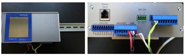
3.2 Power supply
A power supply adapter is included. The power socket of the Q.station has four plugs, of which two plugs are provided for the Q.Station and another two plugs are there for power from the Q.Station to the base socket. The power lines are internally connected. The green and yellow wires are used to connect the UARTs. UART B1 and A1 in the Q.station and UART B1 and A1 of the base socket are connected. The following figure shows the connections diagram of the Q.station, adapter and the Q.bloxx modules.
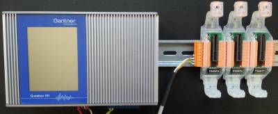
3.3 Connecting the base
The base is used to supply the current and voltage to the module and for data transfer. The modules are electrically connected to the mounting rail (35 mm rail according to DIN EN 60715) by means of a metal spring in the base. Hang the base over the upper part of the rail and press it downwards until the latching cam locks in. An additional base can be mounted and pushed to the left of the existing base. The power is supplied from the left side. These modules are not yet configured. The bases are connected together with the help of the right extension socket. At UART1, a maximum of 16 modules can be connected. The Q.bloxx A127 and Q.bloxx D101 module is then fixed over the base. Then the adapter may be switched on and the Ethernet cable can be connected with the Q.station. This is the initial connection. The address of the module is set over the base, and all other configurations are adjusted on the PC.
4 Configuring the Q.bloxx modules
Before connecting the base with the PC via Ethernet, the base of modules must be assigned addresses. The addresses of the modules are set over the base. The operating mode is configured over the DIP switches on the base.
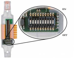
There are 10 DIP switches in a module socket. The switches 1 to 6 are for addressing. Switch 7 is currently not in use, switch 8 is for activating or deactivating Hot swap (factory setting); switch 9 and 10 are for bus termination. The terminal module's 9th and 10th DIP switch should be in ON state which ensures that there is no other module connected further in the bus.
At the beginning, the socket has no configuration. The address of the bases can be given in two ways:
- Manual addressing by DIP switching or
- Using test.commander
4.1 Manual Addressing
Up to 16 modules can be connected in UART 1. So one must give an address starting from 1. For the current application three modules are connected, which can be given an address from 1 to 3. The switches 1 to 6 should be kept in the following way:
| Address | S1 | S2 | S3 | S4 | S5 | S6 |
|---|---|---|---|---|---|---|
| 0 | OFF* | OFF | OFF | OFF | OFF | OFF |
| 1 | ON* | OFF | OFF | OFF | OFF | OFF |
| 2 | OFF | ON | OFF | OFF | OFF | OFF |
| 3 | ON | ON | OFF | OFF | OFF | OFF |
| 4 | OFF | OFF | ON | OFF | OFF | OFF |
| 5 | ON | OFF | ON | OFF | OFF | OFF |
| ... | ... | ... | ... | ... | ... | ... |
| 30 | OFF | ON | ON | ON | ON | OFF |
| 31 | ON | ON | ON | ON | ON | OFF |
| 32 | OFF | OFF | OFF | OFF | OFF | ON |
* OFF = Switch down; ON = Switch up
The base socket of the first A127 module may be given address 1, followed by address 2 and 3 for the modules A127 and D101.
Hot Swap:
This is a function which helps to load the configuration from the EPROM socket to the module and vice-versa. This is controlled by switch 8:
- When switch 8 is OFF, hot swap is activated. If the socket is loaded with a valid configuration in test.commander, then only the module which is compatible to the configuration in the socket can be inserted. The module will be loaded from the socket with the corresponding configuration. While changing the defective module, the active socket module will load the configuration automatically.
→ f.e.: With an active hot swap: If a socket containing the configuration of the A127 module is inserted in another module, an error window will be shown.
- When switch 8 is ON, hot swap is deactivated. Any configuration in EPROM (in the socket) is not read and the configuration of the module connected to the socket is read. After inserting a module, the module configuration is automatically transferred and saved into the socket. So the same configuration is present in the socket and the module.
4.2 Connection buildup with test.commander
Download test.commander example project:
The address of the socket or base module can be assigned via test.commander. For that matter, an Ethernet connection between the PC and Q.station must be established. Download and Install test.commander (actual version 1.7.6 B01) from this link http://www.gantner-instruments.com/software/test-commander.
The connection can be built up with and without a server connection.
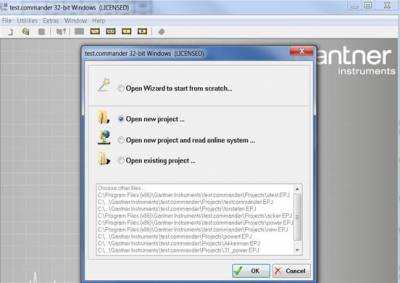
4.2.1 Connection buildup with server
When there is a server, the Q.station uses DHCP (Dynamic Host Configuration Protocol) to obtain an address from the server in the network. In this case, the Q.station just has to be connected to an Ethernet switch. An IP address is automatically assigned. The PC or laptop which is also connected to the same network can access the controller via test.commander. A new project in test.commander must be opened. With a right-click → Add online controller, the Q.station 101 which is in the network can be added.
Further configuration can be done later. The following method may be skipped in case the first way was successful.
4.2.2 Connection buildup without server
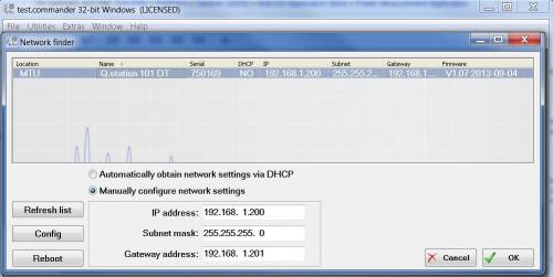
When there is no server in the network, the Q.station can directly be connected to the PC with a cross-over or Ethernet cable. Usually the controller does not receive the IP address of the PC with DHCP. A static IP (E.g.: 192.168.1.20) may be given to the controller via network setting on the Q.station’s HMI screen. The PC IP address can also be changed to 192.168.1.30. Note that the first three sections of the IP address should be the same and only the last two digits can be changed. Now the network can be scanned using test.commander.
In case the Add online controller does not work in test.commander, the user must click on Utilities → Controller network terminal. In that way the user can find the controller with any IP address. Then the user has to select Manually configure network settings and specify the required IP address, sub-net mask and if necessary Default gateway.
After establishing the connection → Add Online controller function will work and controller can be added from the scanned list. The Addressing of modules can be done in following manner.
4.3 Addressing modules
Once the connection is made between the Q.station and the PC with or without the server, the following steps may be taken to address modules via test.commander:
a) Open test.commander and click Utilities → select Slave Setup Assistant..
b) Click Perform scan which will open a new window.
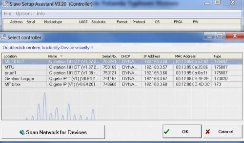
c) Select the controller → click Ok.
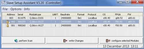
d) From the above slave setup assistant, one can see, that there is a lock symbol at some modules. The lock symbol tells you, that the particular module is already given an address over the DIP switch. The physical address, which was not assigned at the DIP switch, can be given an address via test.commander. The DIP switch (1 to 6), which is meant for the address should be zero, which will enable the user to assign an address via test.commander.
⇒ Lock symbol is shown: Address has already been assigned using DIP switch.
⇒ No symbol is shown: Address has to be set via test.commander.
e) Click on the address number of the module which has no lock symbol. Select the address without conflicting with another module. Click Write changes*.
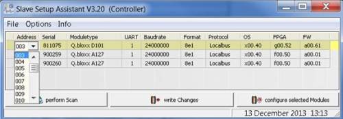
f) That way, the address can be assigned to the socket of the modules.
4.4 Configuration of modules in test.commander
Once the online controller and the modules are added in the test.commander project, the following things have to be accomplished to configure the variables in the module.
a) In the test.commander project the controller and modules are displayed in following way.
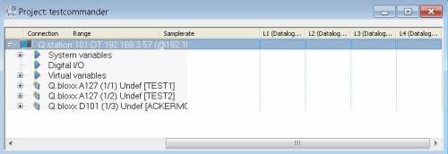
b) Double click the module A127 → ICP100 module configuration window will be opened.
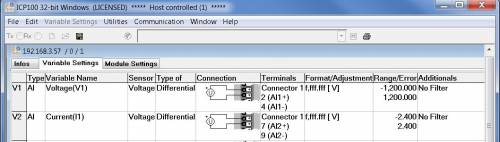
c) Keep the cursor over the Type column → right click →Analog Input
d) Variable Name, Format and range can be adjusted.
e) Several set point variables are also added to visualize the graph in test.viewer.
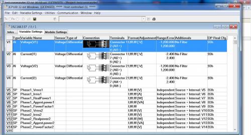
f) The terminal of each variable is shown in the ICP100 configuration window, which helps connecting the input with the proper terminals.
g) In the same way D101 is configured.
The test.commander configuration project can be downloaded here and ran in test.commander.
5 Physical Connection
The current and voltage can directly be connected to the Q.bloxx 127 module, unless until it is in the permissible limit of the module. In case of high voltages and current, the potential transformer (PT) and current transformer (CT) are used to step down the voltage. This will simplify the calculation of high voltages and current.
Following is the circuit to be considered:
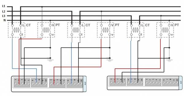
- From the ICP-100 configuration software the terminal connection of variables are known.
- The voltage of phase 1 is connected with terminal 2 (AI+) 4 (AI-) of first A-127 module (connector 1)
- The current of phase 1 is connected with terminal 7 (Ai+) 9 (AI-) of first A-127 module (connector 1)
- The voltage of phase 2 is connected with terminal 2 (AI+) 4 (AI-) of first A-127 module (connector 2)
- The current of phase 2 is connected with terminal 7 (Ai+) 9 (AI-) of first A-127 module (connector 2)
- The voltage of phase 3 is connected with terminal 2 (AI+) 4 (AI-) of second A-127 module (connector 1)
- The current of phase 3 is connected with terminal 7 (Ai+) 9 (AI-) of second A-127 module (connector 1)
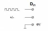
- The Hall effect sensor output is connected with Connector 6 (DI+) & 8 (DI+) 10 (DI-) of D-101 module (connector 1)
- The Hall effect sensor output is connected with Connector 6 (DI+) (DI+) 10 (DI-) of D-101 module (connector 2)
The Hall effect sensor only has one digital output, the same signal is connected to the three digital inputs of D-101.
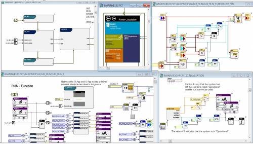
6 Software Programming
With test.con Gantner Instruments is providing a very simple and efficient software tool for application programming. Genereally, the application has two parts, one is the real time kernel which gets the direct input from the modules and the other is the user kernel which comes with HMI design facilities. Further details about creating a Real-time and User Space application can be seen under this link → Installation and first steps.
6.1 Program the real-time kernel
You can also have a look at the tutorial video from the video series "test.con 6 part 1: program a real-time kernel in the Q.station".
Content
- Structure of the Q.station (00:20)
- Adjust cycle time in test.commander (00:56)
- Introduction in test.con and the real-time application (01:13)
- Program real-time kernel (Example: Q.station and tweezers with strain gauge) (04:06)
If the video does not work, you can click here to watch.
6.2 Create a user-space application
In the video tutorial "program a user-space application" you will get to know how and why you need to create a user-space application.
Content
- Introduction
- Create user space project with simple HMI interface (screen of the Q.station) (00:30)
- HMI blocks in the favorites tree -> display programming (HMI) (03:45)
- Create simple HMI design (04:25)
- Connect the HMI object (display on the screen) with application connectors (07:45)
Steps for display programming
- Configure max value (04:15)
- Configure min value (10:48)
- Button block to reset values (12:00)
- Configure and connect trend block
- Upload program into the Q.station (15:35)
If the video does not work, you can click here to watch.
6.3 Application example power measurement

The power measurement application can be downloaded here:
[Please be aware that the application has been developed with test.con 5 and is not quite compatible with test.con 6]
The following steps may be taken to install and run the application:
a) Download the project and extract the zip file to a specific folder (more detailed information → Installation and First Steps).
b) Double click the folder → Open PowerRealTimeProject → Double click MDL, which is the real-time project.
c) Click Tools → Network PAC-Scanner → Select the configured Q.station by checking the IP address → Press OK
d) Click Run → Enter to open Run-mode. Click Run → Logon to Target System
e) Select the Target system (MK175RT) → click Connect
f) Click Run→ Select Download.
In the same way, the User Space Kernel project can be downloaded and run in the target system.
a) Open the User Space Kernel project in the folder PowerUserKernel → MDL
b) The above steps may be followed to establish a connection with the Q.station.
c) Go to run mode and connect to the User Space Kernel (MK175USR).
d) Download the project.
Both the real-time and user-space application must be in the same directory.
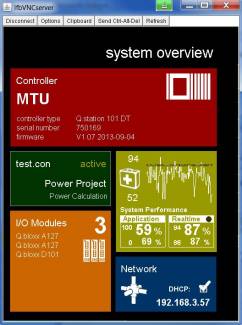
7 Results and Visualization
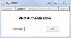
The results can be visualized on the HMI screen or on a PC, which is connected to the same network. The Q.station 101 DT comes with an HMI screen, and the user can get the values of all the desired variables from the display. The Q.station has the option to connect an external display as well. Apart from displays, the Q.station supports VNC (Virtual Networking Computing), too. By using the VNC server in the Q.station, we can connect the HMI screen with the PC. The server allows the VNC client, i.e. the PC to takes control of the Q.station. The VNC client is the program that watches, interacts and controls the server.
The connection can be made just by typing the IP address of the server (with a default port 5800) in the browser. The following steps may be taken to reach a connection:
a) Open an internet browser and type the IP address with the 5800 port name at the end, like this: http://192.168.3.51:5800/.
b) A pop up will come for acceptance to run the program, accept and click OK.
c) The following window will ask for password. Enter master → Click OK.
d) Then the screen of the Q.station can be visualized like this:
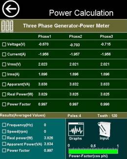
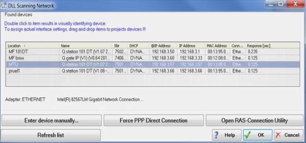
The waveform of the output and input signal can visualized in test.viewer. Open the test.commander project → click Read Online Values from Controller.
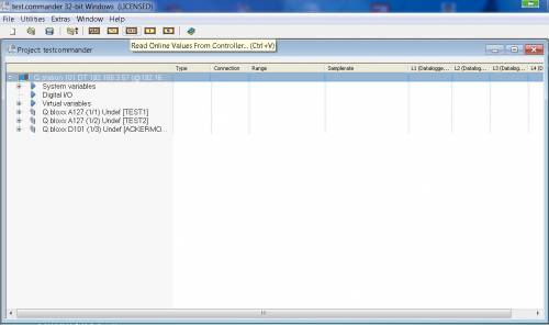
Then a DLL Scanner window will be opened, where the user has to select the controller. The following window will appear after selecting the controller:
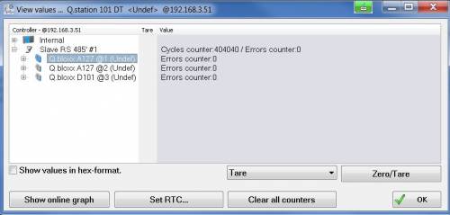
Click Show Online Graph → test.viewer will be opened where online graph and values can be seen.


In this way, a power measurement and observation can be accomplished. If you have any questions or issues do not hesitate to contact Gantner Instruments (testing@gantner-instruments.com).