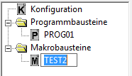
Program and macro blocks
1 General

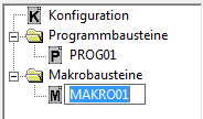
Program blocks serve to define the behavior of individual tasks in the target system. Macro blocks contain sub functions and serve modularization. As the system facilitates multiple calling of structure blocks with different parameter sets, it distinguishes between classes and instances.
The classes of macro and program blocks are edited in the worksheet windows in edit mode. Menu commands or the project tree can be used to create or import new structure blocks and edit, copy, delete, rename, export or change the appearance of existing structure blocks.
The following operations do not refer to individual calls of structure blocks in the project, but to their definition through contained blocks as well as display and access settings.
2 Conventions for designation
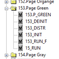
Macros must have unique names. To keep the names simple, all page names should start with a 3-sign prefix. In experience, numbering the pages is a reliable method.
Example:
<xxx>.Pagename:
- <xxx>_INIT
- <xxx>_RUN
- ...
- Designations of structure blocks only consist of capital letters.
- They may comprise up to 14 characters.
- Blank characters are not allowed in the name.
- Program blocks are characterized by the prefix $.
- The configuration has the designation &MAIN.
- Designations of macro blocks must not use & and $ as the first character.
- For program blocks the use of & as the first character is not permitted.
3 Create structure blocks
Procedure

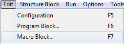
1. Call the "Program Block" or "Macro Block" commands in the Edit submenu
The commands above can be called in edit or run modes. After a name has been specified, the system automatically changes to edit mode.
The according keyboard shortcuts can be used, too.
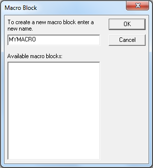
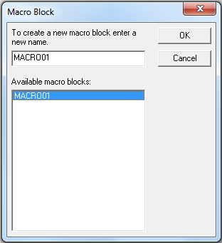
2. Enter the name
A dialog opens where a designation can be entered in the input field (refer to the Conventions for Designation section). Such designation must not be contained in the underlying list of existing program or macro blocks.
3. Edit the structure block
After confirming the entry with OK, the dialog is closed and a new structure block is created. An empty worksheet window indicating the entered designation in its title bar is opened and can be edited.
OR
1. Call the context menu of a folder in the project tree
The context menu opens when the cursor in the Edit mode is on a folder of the project tree and the right mouse button is pressed.
2. Call the "New Program" or "New Macro" commands
3. Change the name
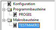
Calling the command, an empty worksheet window is created and a new entry is generated in the project tree. The proposed name can be changed in the input field of the project tree to describe the structure block's function.
4. Edit the structure block
Upon confirming the entry by pressing the Enter key, the title of the new worksheet window is adjusted and you can start to edit the structure block.
4 Edit structure blocks
Procedure
1. Call the Configuration, Program Block, or Macro Block commands in the Edit submenu
The above commands can be called in edit or run modes. The system automatically changes to edit mode as soon as the structure block has been selected. When Configuration is called, the relating window opens immediately.
The according keyboard shortcuts can be used.
2. Select the structure block
Select an entry from the list of existing program or macro blocks in the opened dialog.
3. Edit the structure block
Upon confirming the entry by pressing OK or double-clicking on the entry, the dialog is closed and the worksheet window of the structure block opens. Windows, which have already been opened, are activated by this command and displayed in the foreground. Now, new blocks can be inserted in this worksheet and existing blocks can be linked or deleted.
OR
1. Double-click on the designation of the structure block in the project tree
By double-clicking with the left mouse button on the designation of the program or macro block or the configuration entry in the project tree, the relating worksheet window is opened or activated.
5 Copy structure blocks
Procedure
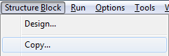
1. Call the Copy command in the Structure Block submenu
Copying of structure block definitions is only possible in edit mode.
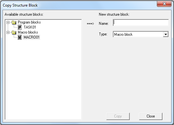
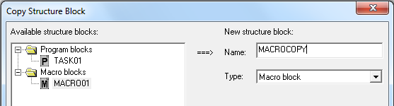
2. Select the structure block to be copied
A dialog opens with a list on the left displaying the structure blocks defined in the project. Select the source for the copying process from this list.
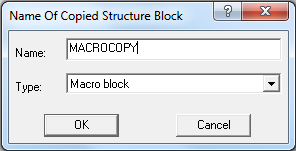
3. Enter the name of the new structure block
An input field is displayed on the right where the name of the new structure block can be entered. The entered name must comply with the conventions for structure blocks and must not be used yet by any other block of the same type.
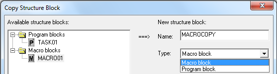
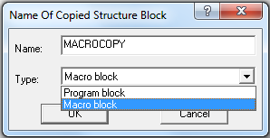
4. Specify the type of the new structure block
As a type macro block and program block can be selected in the drop-down list field.
5. Copy the structure block
By pressing Copy, a new structure block is created with the same definition and the same display features as the source block, and the list of existing structure blocks is updated.
6. Close the dialog
After completion of the copying process, the operation can be repeated or the dialog be closed by using the button of the same name.
OR
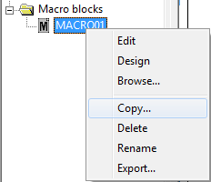
1. Call the context menu of a program or macro block in the project tree
The context menu opens when the cursor in the Edit mode is on the program block or macro block entry in the project tree and the right mouse button is pressed.
2. Call the Copy command
3. Enter the name of the new structure block
Enter the name of the new structure block in the input field of the opened dialog. This name must not have been used and must comply with the conventions.
4. Specify the type of the new structure block
As a type macro block and program block can be selected in the drop-down list field.
5. Copy the structure block
Upon confirming the entry by pressing OK, the block selected in the project tree is copied and the dialog is closed. The list of structure blocks in the project tree is updated and you may proceed with editing.
6 Delete structure blocks
Procedure
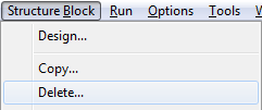
1. Call the Delete command in the Structure Block submenu
Structure blocks can only be deleted when the system is in the Edit state.
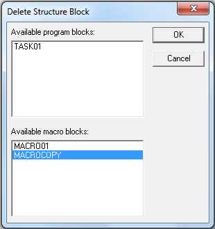
2. Select the structure blocks to be deleted
Program and macro blocks defined in the project are displayed in two lists arranged above each other. Similar to other applications, several entries may be selected or individual entries deselected by pressing the left mouse button and by concurrently pressing of Ctrl or Shift.
3. Delete structure blocks
Upon pressing the OK button the structure block definitions and their calls are deleted from the project. Thereafter, the dialog is closed and editing may be continued.
OR
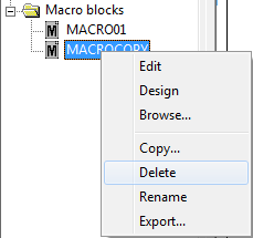
1. Call the context menu of a program or macro block in the project tree
The context menu opens when the cursor in the Edit mode is on the program block or macro block entry in the project tree and the right mouse button is pressed.
2. Call the Rename command
7 Replace structure blocks
Procedure
1. Call the context menu of a program or macro block in the project tree
The context menu opens when the cursor in the Edit mode is on the program block or macro block entry in the project tree and the right mouse button is pressed.
2. Call the Replace command
After calling the entry "replace" the parameter dialog for replacing opens. Here, you can use a drop-down menu to select a block which shall replace the original block. With the present checkbox you can determine if appropriate instance parameters (if the call name matches) are adopted with the new macro or not.
8 Rename structure blocks
Procedure
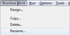
1. Call the Rename command in the Structure Block submenu
The designation of structure block class can only be changed in edit mode.
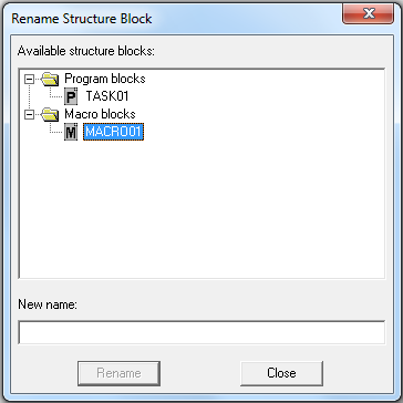
2. Selection of the structure block
A dialog opens displaying all existing structure blocks. Select a macro or program block from the list.
3. Enter the new name
The new name of the structure block class is entered in the input field below the list. Care must be exercised as to ensure that there is no block of the same name and the same type. In addition, the conventions for structure block designations must be complied with.
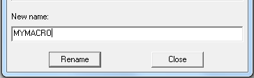
4. Rename the structure block
The name is changed by calling Rename. The entries in the list are updated accordingly.
5. Close the dialog
Now, other structure blocks may be renamed. Pressing Close terminates work in this dialog.
OR

1. Call the context menu of a program or macro block in the project tree
The context menu opens when the cursor in the Edit mode is on the program block or macro block entry in the project tree and the right mouse button is pressed.
2. Call the Rename command
3. Enter the new name
After calling this command, an input field is created instead of the entry, where the new name can be typed. This new name must comply with the requirements indicated above. Upon pressing the Enter key, the change is accepted. By pressing Esc, the input field can be closed without any new name entered.
9 Export structure blocks
Procedure
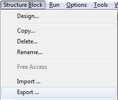
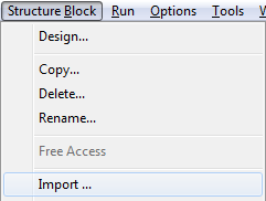
1. Call the Export command in the Structure Block submenu
Program and macro blocks can only be exported in edit mode.
2. Selection of the structure block or structure block tree
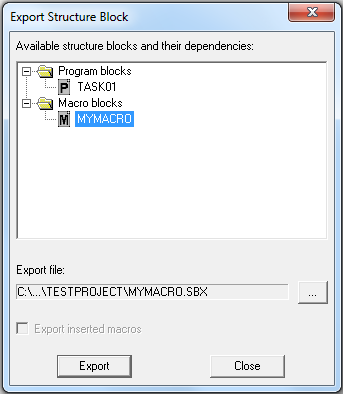
The called dialog contains an overview of all program and macro blocks defined in the project. The hierarchical relations of the structure blocks are represented as a tree. A structure block or partial tree is selected for the export by marking the name.
3. Enter the export file
After the selection of a structure block an export file of the same name located in the project directory is automatically suggested. It is displayed in the field under the structure block overview. A file dialog which allows the selection of another directory or another file is opened over the button next to the field.
4. Switch "Export inserted macros"
Whether only the selected structure block or also all contained macros defined in the project shall be exported is defined with the mentioned switch.
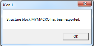
5. Export
By calling the Export command the instructions for creating the selected structure blocks, the contained blocks and their connections as well as the belonging settings are written into the file.
6. Close the dialog
In the same way other structure blocks and hierarchies can be exported now into files. The button with the same name is used for closing the dialog.
OR
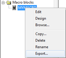
1. Call the context menu of a program or macro block in the project tree
The context menu opens when the cursor in the Edit mode is on a program block or macro block entry in the project tree and the right mouse button is pressed.
2. Call the Export command
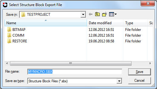
3. Select the export file
The file dialog opened by the command is used for entering the export file name. A suggestion for the file name is formed from the designation of the selected structure block. File name and directory can be changed in the dialog.
4. Export
After pressing the Save button whether only the block itself or the complete hierarchy shall be exported is queried at structure blocks which contain calls of other structure blocks defined in the project. Otherwise or after defining the export size the information needed for restoring the structure blocks is written into the file.
10 Import structure blocks
Procedure
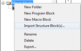
1. Call the Import command in the Structure Block submenu or in the context menu for a folder in the project tree
Structure blocks can only be imported when the system is in the Edit state. When the cursor is on a folder of the project tree and the right mouse button is pressed the context menu opens.
2. Select the import file
With the command a file dialog is called where export files for structure blocks which were created with the programming system can be opened. (see Export Structure Blocks)
3. Import
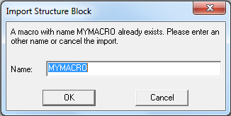
After selecting an export file and pressing the open button the file dialog is closed and the import runs. During the import the instructions saved in the file are executed to create the structure blocks as well as the blocks and connections contained in them. At this, messages point to possible problems, like not loaded libraries or conflicts with used designations. The two mentioned problems can be easily solved with automatically opening dialogs.
If the import was successfully executed, the newly inserted program and macro blocks can be used over the project tree. Now the imported structure blocks are part of the project. So they can be used and edited without reservations.
11 Structure block design
This section describes first how the structure block design can be called.
Procedure
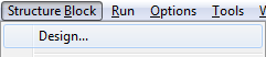
1. Call the Design command in the Structure Block submenu
The above command can be called in edit and run modes. When a structure block has been selected, the system automatically changes to edit mode.
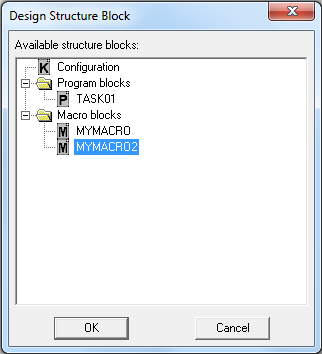
2. Selection of the structure block
A dialog opens, displaying all structure blocks (including the configuration) contained in the project. However, design of configuration is only useful for specifying display options for the relating worksheet window. The configuration symbol only appears in the design window.
3. Open the design window
After selecting a structure block and pressing OK, the dialog is closed and the Design window with the block symbol opens. In addition, a second toolbar is generated, containing commands for working on the symbol and the presentation in the worksheet window.
OR
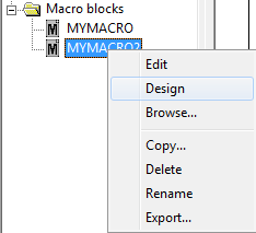
1. Call the context menu of a structure block in the project tree
The context menu opens when the cursor in the Edit mode is on the program block or macro block entry or on the configuration entry in the project tree and the right mouse button is pressed.
2. Call the Design command
With this command, the design window opens and the second toolbar is generated.
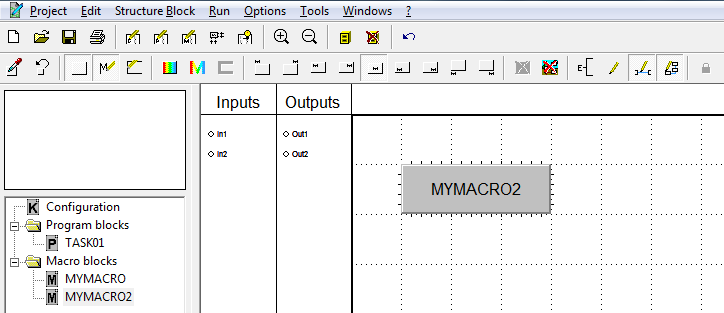
The design window has the following view:
The sections below list options for operations to change the symbol of the structure block and presentation in its worksheet window.
Change the symbol size
The size of the symbol should be defined in the first step at the development of a structure block because connections might be wrongly displayed when changing the size of a structure block already called. The width and the height can be concurrently changed by dragging the lower right corner using the mouse; drag the right side for changing the width, and the bottom for changing the height.
Position inputs and outputs on the block frame
The Inputs and Outputs tables list the connectors inserted in the Edit mode, which have not yet been assigned any position on the frame of the symbol. A connector is grabbed by clicking on it with the left mouse button. Thereafter, it can be dragged over to the block frame by holding down the button, and dropped there.
Signal inputs should be placed on the left edge and outputs on the right edge of the symbol. Parameter inputs should be arranged on the bottom edge.
Define as design template ![]()
The actual design is defined as design template.
Reset to design template ![]()
Reset the actual design to the design template.
Button style ![]()
The symbol of a newly created structure block appears as a gray rectangular button. If the button's display is deactivated, the symbol becomes transparent and can be assigned a bitmap.
Name ![]()
The designation of new structure blocks is displayed in the middle of the symbol. The display of the designation can be deactivated by means of the name button in the toolbar.
Frame ![]()
Symbols of newly created structure blocks have a thick black frame. The frame can be deactivated by means of the frame button in the toolbar.
Background color of symbol ![]()
This button opens a color dialog for the background.
Text color of symbol ![]()
This button opens a color dialog for the text.
Frame color of symbol ![]()
This button opens a color dialog for setting the background.
Position of name ![]()
The display of the designation can be controlled by means of various buttons in the toolbar and can appear inside or outside the symbol.
Bitmap for structure block symbol ![]()
With this function a structure block can be assigned a bitmap as a symbol. This function can be only called if the button display is deactivated (refer to above). To adjust the block symbol to the bitmap such that the bitmap is displayed in its original size at a zoom factor of 1.00, activate the "Change block size to bitmap size" option in the dialog window.
Background picture for structure blocks ![]()
With this function the worksheet window is assigned a bitmap as a background image. For simple operation and observation functions, the static part of the image can be implemented by means of this bitmap. By using this function, macro blocks can be created which serve exclusively documentation purposes.
Connector labels inside or outside ![]()
This button is used to define the position of the connector designations. Normally they are displayed outside the structure block. By setting the option the names are turned inside and appear behind the pin.
Designations which are located within the block are also represented when display of connector labels is deactivated.
Visualization flag ![]()
In the Edit mode all blocks and connecting lines are always visible in the worksheet windows. In the Run mode individual components can be hidden. Hence, it is possible to display only components relevant to operating and observation functions.
The display of blocks in the worksheet window can be switched off by the button “Show blocks”. This option is useful, for instance, when only dynamic visualization functions are to be displayed. If the block display is switched off only blocks with the activated visualization flag are displayed. The visualization flag of structure is set by using the button.
Example:
To display only the structure block call M2 in a structure block M_PAR with the two structure block calls M1 and M2, the display of the signal connections and the display of blocks must be deactivated in M_PAR. The visualization flag in the structure block M2 must be activated and the visualization flag in M1 must be deactivated.
For setting the visualization flag for a self implemented function block, the library function “L4 SetVisAlways” have to be used.
Show connections ![]()
In edit mode all connecting lines are always visible in the worksheet windows. In the Run mode individual components can be hidden. Hence, it is possible to display only components relevant to operating and observation functions.
The included connecting lines can be shown or hidden by this button. This option is useful, for instance, when only dynamic visualization functions are to be displayed.
Show blocks ![]()
In edit mode all blocks are always visible in the worksheet windows. In the Run mode individual components can be hidden. Hence, it is possible to display only components relevant to operating and observation functions.
The included blocks can be shown or hidden by this button. This option is useful, for instance, when only dynamic visualization functions are to be displayed.
If the access limitations has been activated in the system, the user is required to log on when starting test.con. If the logged-on user is entitled to call the structure block design, he may restrict access to the structure block in the Run mode to special user groups, by means of this button ![]() .
.
Configure macro design
General settings for the macro design are made in the <project name>.IWS or in the icon.ini file.
Section
[system]
Font and text size of the designation text
| sblockfont | 10,0,Arial | Font size,?,Font |
Font and text size of the Input and Output label
| iolabelfont | 10,0,Arial | Font size,?,Font |
Minimum distance between the Inputs and Outputs
| minsblockiospace | 5 | Distance between the Inputs and Outputs in pixels |
Example
[system]
minsblockiospace=5
iolabelfont=10,0,Arial
sblockfont=10,0,Arial
12 Task properties
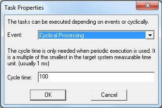
Special properties can be assigned to program blocks for their processing. It can be distinguished between a cyclical and an event oriented processing. The end choice is based on the features of the corresponding target system.
The cycle time is relevant only for periodical processing. It is a multiple of the smallest measurable cycle time of the corresponding target system (in most cases 1ms).
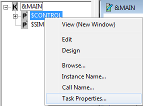
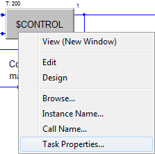
The call of the dialog for the settings of the task properties will execute via a context menu directly in the project tree or on the respective program block.
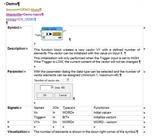
13 Write online help for macro blocks
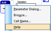
In general, all function blocks have an online help. The help for the block is called over the context menu of the block (right click on the FB). The help content for each block is organized in block libraries. So for each block library there is a help file. The according help for the block is addressed over entry points.
The same mechanism can also be used for linked projects. In such a linked project, a help can be generated for each macro block.
Currently, *.chm files are used to provide the online help.
To be able to address each block, the entry points have to be defined according to defined conventions.
Important: After keyword, the extension –module has to be written behind the block name.
ProSign currently uses the commercial tool “Doc2Help 2008” to create the online help (license necessary).
keyword=<block name or macro>-module
displaytitle=short name
linktag=IDX_<block name>
Necessary configuration
[system]
...
sblockhelp=On
...
The programming system has to be configured accordingly, so the help system also considers macro blocks. It can be configured either globally in the icon.ini file in the BIN directory, or project-specifically in the <project name>.IWS file.
Example